
What is an EC fan? The motor, the drive and why it lives on the hub
Electronically commutated fans put the rectifier, DC bus, inverter and a permanent-magnet rotor inside the fan itself. What that changes versus an AC motor on a VFD, and why the telemetry it reports looks the way it does.
Walk into an AHU plant room built ten years ago and you'll find a belt-driven centrifugal fan, a three-phase induction motor and a VFD in a panel on the wall. Walk into one built this year and the fan is a plug fan with no belt, no external drive and a Modbus port. That is an EC fan, and the difference is worth understanding because it changes what you can measure.
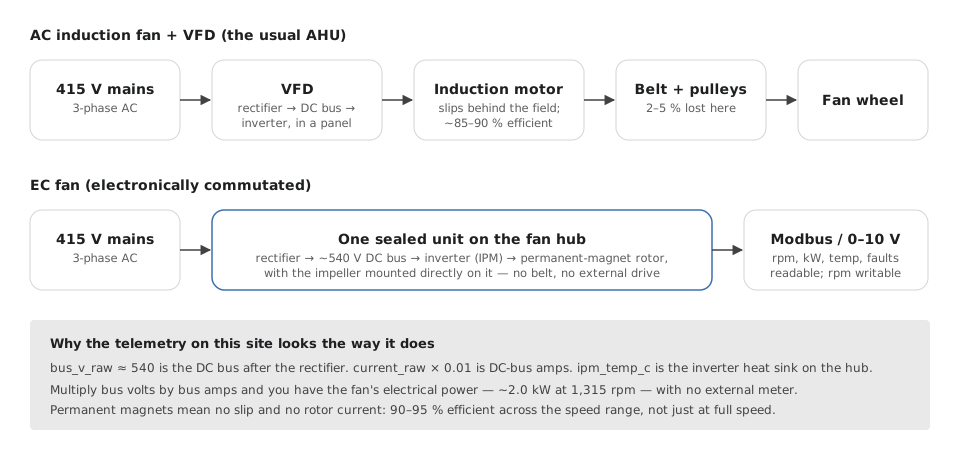
The AC induction motor and VFD
An induction motor spins because a rotating magnetic field in the stator drags the rotor along; the rotor always 'slips' a little behind the field, and that slip is lost as heat. To change speed you change the field's frequency, which is what a VFD does: it rectifies the mains to DC, then chops that DC into a new three-phase AC at whatever frequency you ask for. Add a belt and pulleys to match the motor to the fan, and you have the classic arrangement — about 85–90% efficient at the motor, minus 2–5% in the belt, and a VFD that can be anywhere in the panel.
The EC fan
An EC (electronically commutated) fan keeps the rectifier and the inverter but mounts them in a sealed housing on the fan hub, and replaces the induction rotor with a permanent-magnet rotor. The inverter — an IPM, intelligent power module — switches the stator windings in sequence, electronically, to pull the magnets round. No slip, no rotor current, no belt: the impeller is bolted directly to the rotor. Efficiency sits at 90–95% and, crucially, stays there across the speed range rather than collapsing at low speed the way an induction motor's does.
What that changes in practice
- Speed is set by a signal — 0–10 V or a Modbus register — not by a mechanical pulley ratio. Changing the duty point is a number, not a site visit.
- The drive knows its own electrical state. It reports DC-bus voltage, DC-bus current, inverter temperature, actual rpm and a fault flag, over the same Modbus link.
- Multiply bus volts by bus amps and you have electrical power with no external meter. On the fan this series follows: about 540 V × 3.7 A ≈ 2.0 kW at 1,315 rpm.
- Several EC fans run in a 'fan wall' sharing the load; one failing fan doesn't stop the AHU, and the rest speed up to cover it.
Why the raw registers look like they do
Modbus registers are integers. The fan in our data reports bus_v_raw in the 520–560 range and current_raw in the 360–375 range at the duty point. Those are counts: 1 V per count for the bus and 0.01 A per count for the current. The next post works out why those scales are the only ones that make physical sense — and what a 415 V three-phase supply turns into once it is rectified.