
Anatomy of an air-handling unit: what each section does and what a controller reads
Mixing box, filters, cooling coil, supply fan, plenum. A walk through a commercial AHU from air-in to air-out, and the sensor at each step that tells you whether it is working.
An AHU is a steel box with air going through it. Everything that matters happens in five sections, in order, and each section has a sensor that reports on it. Learn the box and you can read the dashboard.
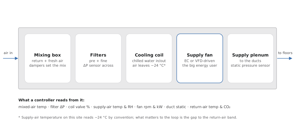
Mixing box
Return air from the floor meets fresh air from outside. Two dampers set the ratio. Minimum fresh air is set by occupancy (see the IAQ post); more is opened when outdoor conditions make it cheaper than return air (free cooling) or when CO₂ demands it. Sensor: mixed-air temperature, and the damper positions.
Filters
Pre-filter (coarse) then fine filter. The ΔP sensor across the bank is the one that pays for itself: a loaded filter means the fan works harder for the same air, and on an EC fan you can see it directly as extra kW at the same rpm. Sensor: differential pressure across the filters.
Cooling coil
Chilled water (6–8 °C leaving the chiller, warmer by the time it reaches the top floor) flows through finned tubes; air passes across them and gives up heat and moisture. The control valve modulates water flow to hit the supply-air target. A valve at 100% with the supply air still too warm means the coil cannot do what is asked — water too warm, too little flow, air lock, fouled fins — and that is exactly the Insight the system writes. Sensors: chilled-water supply and return temperature, valve position, supply-air temperature and humidity.
Supply fan
The energy user. Either an AC induction motor on a VFD and a belt, or increasingly an EC fan with the motor built into the hub. The fan is controlled to hold a duct static-pressure setpoint — enough pressure that the farthest diffuser still gets air — and that setpoint is where most of the waste hides, because it was chosen on commissioning day for the worst case and never revisited. Sensors: rpm, kW (or bus volts × amps on an EC fan), motor/inverter temperature, status, fault.
Supply plenum and ducts
Conditioned air leaves the box into the main duct, past the static-pressure sensor, and on to the floors through VAV boxes or diffusers. Sensors: duct static pressure, and the return-air temperature and CO₂ that close the loop.
Reading an AHU from its numbers
- Return air above band + valve at 100% → the coil is at its limit. Look at chilled-water temperature first.
- Fan rpm high + static pressure low → something downstream is open or leaking, or a filter/coil is blocked upstream.
- Filter ΔP rising week on week → schedule the change before the fan energy pays for it twice.
- Fan at 100% + return air fine → the static setpoint is too high. Free money.
The next posts go inside the fan — the part that turns the most electricity into the most air — starting with what an EC fan actually is.