
Electrical basics for HVAC technicians: contactors, capacitors, relays and the multimeter
The three components behind most 'it won't start' calls, the four multimeter measurements that find the fault, and the safety habits that keep you and the meter alive.
Most HVAC service calls are electrical before they are mechanical. The compressor that 'won't start' usually has nothing wrong with the compressor. Three components and one instrument cover most of it.
The control chain
A thermostat or BMS output makes a 24 V 'call'. That call drives a relay. The relay's contacts close the 24 V coil of a contactor. The contactor's heavy contacts close 415 V (or 230 V) onto the motor. Low voltage decides; high voltage does the work. When something doesn't run, walk the chain in that order.
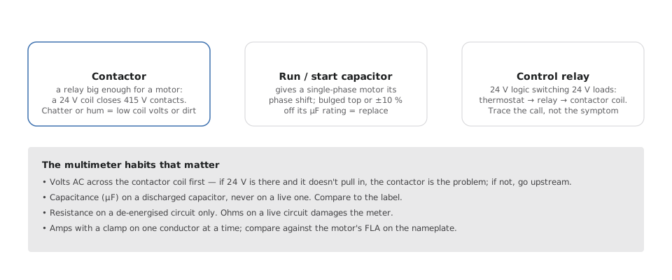
Contactor
A relay big enough for a motor. A small coil (24 V, sometimes 230 V) pulls in a set of contacts rated for the motor's full-load amps. Pitted contacts, a weak coil or dirt in the mechanism cause chatter, humming, or one phase not making — which cooks a three-phase motor. Measure coil volts first: if 24 V is present and it doesn't pull in, the contactor has failed; if it isn't, the problem is upstream.
Run and start capacitors
Single-phase motors need a phase shift to start turning; the capacitor provides it. A start capacitor gives a big kick for a moment; a run capacitor stays in circuit. A bulged top or a capacitance reading more than 10% off the label means replace it. Measure only after discharging — a charged capacitor will spot-weld your probes.
Control relays
24 V logic switching 24 V loads: thermostat to relay to contactor coil. Cheap, numerous, and a common point of failure in older panels. Listen for the click; measure across the contacts.
The four measurements
- Volts AC, live, across the component that should be energised. Is the signal arriving?
- Capacitance (µF), on a discharged capacitor, compared to the label.
- Resistance (Ω), on a de-energised circuit only, for windings and continuity. Ohms on a live circuit destroys the meter.
- Amps, with a clamp on one conductor at a time, compared to the motor's FLA on the nameplate. Over FLA means a mechanical load problem or a failing winding.
Safety that is not optional
- Lock out and tag the isolator before opening a panel. Verify dead with the meter you have just proven on a live source.
- Discharge capacitors through a resistor, not a screwdriver.
- Three-phase: check all three phases are present and balanced before blaming the motor. A lost phase on a running motor is the most common way a compressor dies.
Modern EC fans move most of this inside the fan hub — there is no contactor or capacitor to replace, and the drive reports its own bus voltage, current and temperature. That is the subject of the EC-fan series.